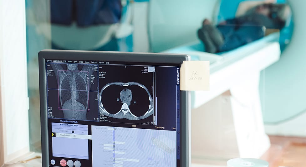
Magnetic Resonance Imaging equipment or what we like to call the black box of doom has a long history of being intimidating due to the stories of the magnet pulling conductive materials in towards the core. However, its use and safety has increased over time. Make a point to never enter a Magnet Room without the guidance of a qualified technician that oversees this equipment. If no one is around, “DO NOT GO IN”!
“Nothing in life is to be feared. It is only to be understood”.
– Marie Curie
In recent years, the installation of MRI (Magnetic Resonance Imaging) machines has increased in research and healthcare facilities. The growing research and healthcare industries benefit both the patient and the researcher in identification of abnormalities in cell or tissue structure. Some primary reasons for this increase are the wide range of usage with more advanced technology and the ease of maintaining and installing the equipment.
What does an MRI actually do?
An MRI machine creates images of organs and soft tissue within the body. By creating a strong magnetic field around the body, the atoms are knocked off-axis by the field variance. As the atoms shift, they emit small radio frequency energy. The radio frequency energy emissions are measured and enhanced using computer software. The imaging software then creates a map of the designated area of the body, detecting changes in tissue density and thus indicating pathological abnormalities.
How does an MRI relate to HVAC?
The MRI magnet generates strong fields to cause atoms to resonate. This is accomplished by using coil windings made of superconductive materials. These materials, when cooled down to -270°C, can conduct electrical current with near zero resistance. To cool down the superconductive material, a cooling system has to be in place. The use of cryogenic liquid helium is utilized to keep the magnet at the optimum temperature by circulating the helium through an insulated jacket surrounding the superconductive coils. With the cost of liquid helium going up and availability going down, not to mention it being a non-renewable resource, it was necessary to find a secondary cooling source to reduce the amount of liquid helium required to operate an MRI.
Mechanical cooling was introduced through the process of direct expansion chillers to assist in the cooling needs of the MRI machines. Larger healthcare facilities with the availability of a building chilled water source utilizes water to water heat exchangers with a process water loop to maintain MRI equipment cooling needs.
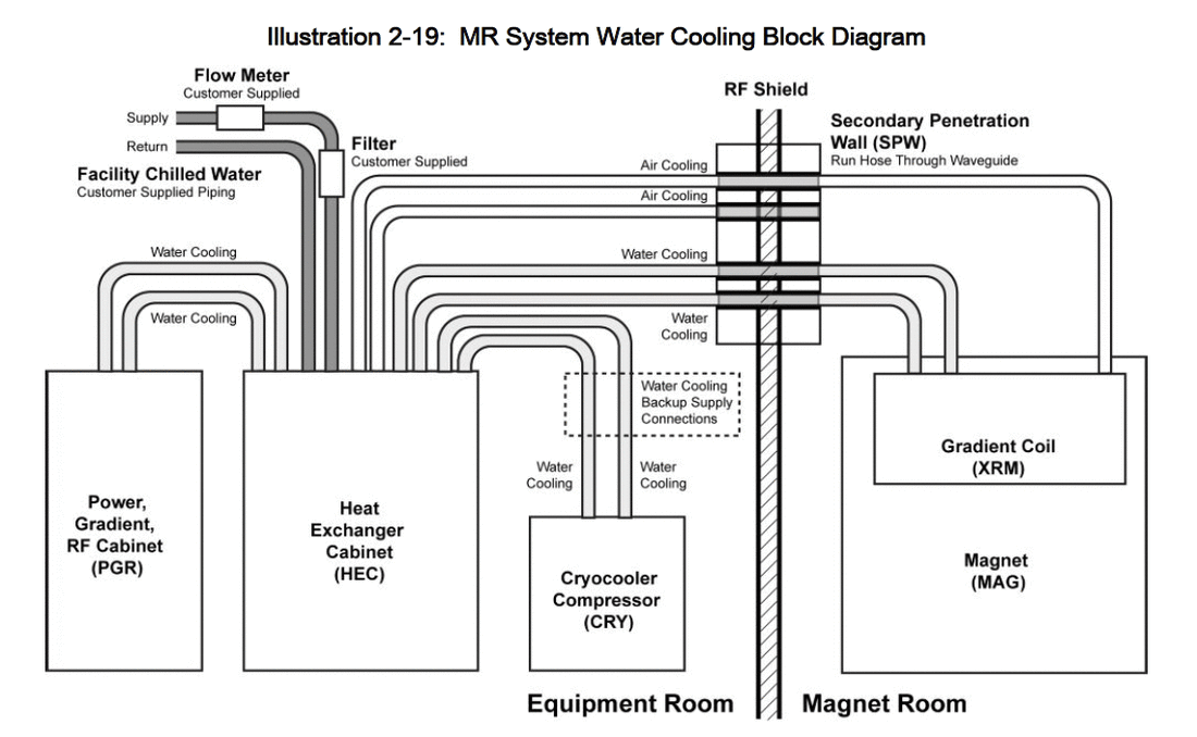
MRI equipment is usually provided to the healthcare facility directly through the manufacturer. The equipment specification sheet contains the following type of information for the engineer to design for: flow rate, water temperature, BTU discharge to water, pressure loss through MRI, maximum water pressure, water quality and filtration requirements.
Two of the biggest questions from a test and balance firm standpoint are “How does the water circulate through this machine?” and “Is it constant?” A schematic of a manufacturer’s plumbing drawing helps us understand a little more of what goes on inside of a machine. Knowing that the MRI machine has its own pumps, bypass valves and heat exchangers helps us understand and appreciate the complexities of this machine.
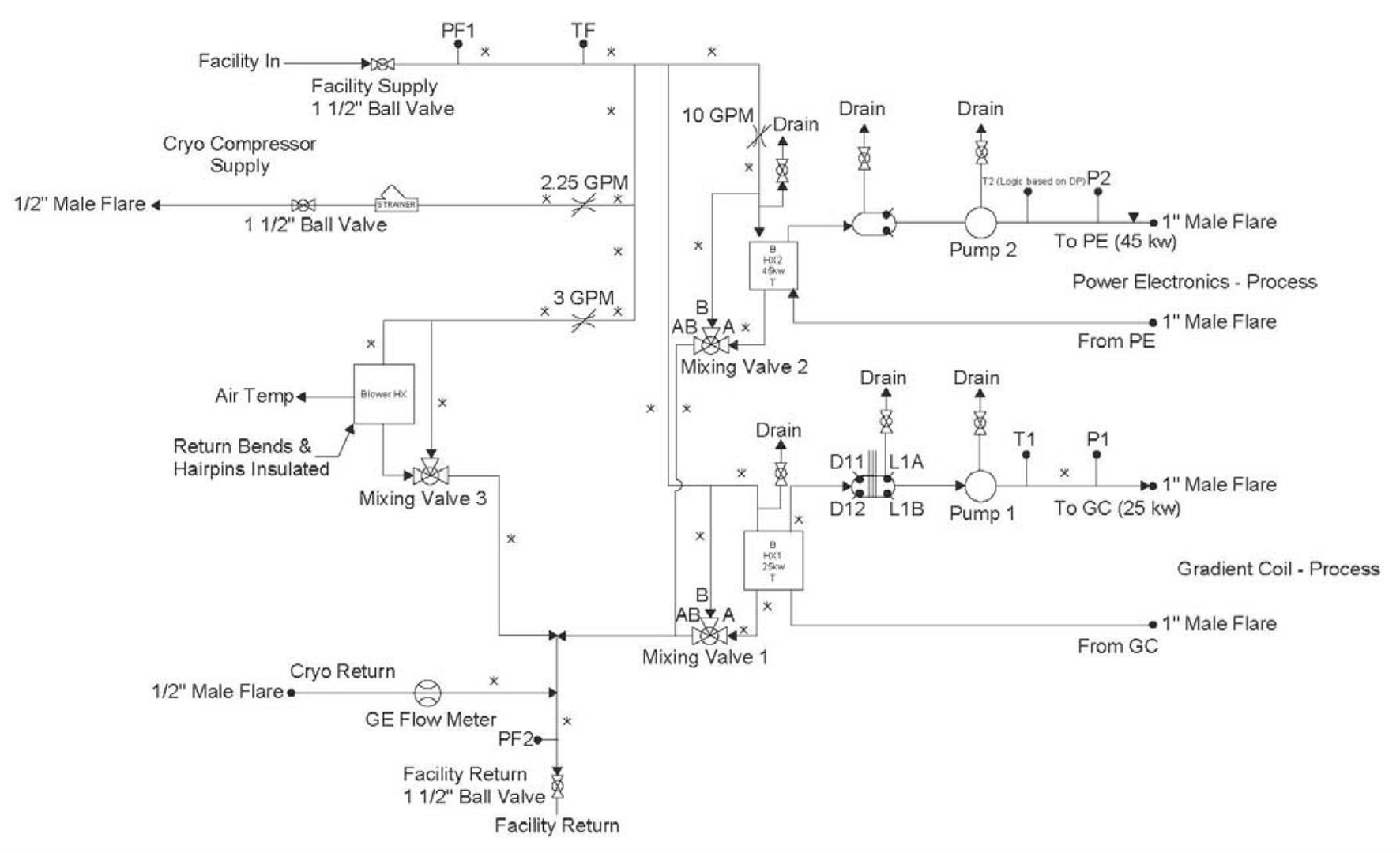
The design for the system usually begins with a process chilled water loop utilizing a lead/lag pump configuration that draws through a water to water heat exchanger. With the use of an ultrasonic flow meter and variable speed pumps, a constant water flow can be continuously maintained to the MRI equipment. Due to the critical nature of the equipment, an N+1 pumping system is installed to ensure continuous operation in the event of pump failure or maintenance. The temperature control loop usually consists of a control valve on the building side of the heat exchanger that modulates to maintain a process chilled water temperature setpoint. A recent concern for process chilled water loops has been the lack of a make-up water source. Over time, the opportunity for leaks can occur or filter and pump maintenance allow water to be removed from the loop and be replaced with air. Without a source of make-up water to refill the lines and bleed out the air, the heat exchanger performance will drop, and the pumps will begin to cavitate.
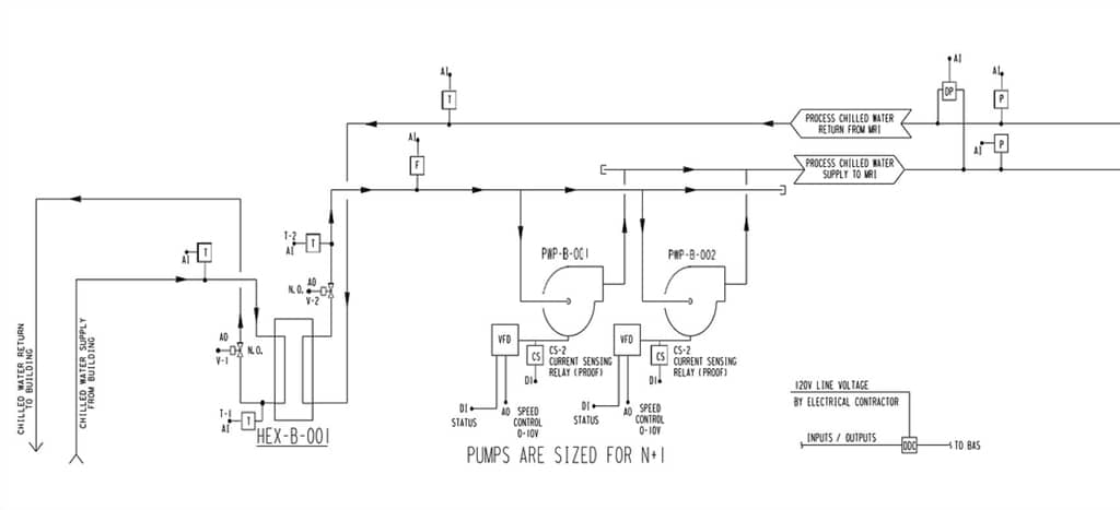
In testing these systems, it is understood that the only way to accurately provide the correct amount of water is to measure it with an ultrasonic meter. If the process loop serves a single MRI machine, the water flow required for most manufacturers’ equipment is usually around 30 GPM. Variable speed drives continually modulate the pump speed to maintain a constant volume of water (even when the inline filters load).
Controlled Bypass Feature
Another feature present in some process water loops serving MRI machines is a “controlled bypass”. This is basically a jumper pipe between the supply and return process water that is controlled by a three-way control valve. The bypass valve will open and close to maintain a differential pressure setpoint between the supply and the return process chilled water loop. This bypass loop is installed primarily for protection of the pumps from “deadheading”.
What is Deadheading in an MRI?
“Deadheading” can occur when the internal MRI equipment filters load, causing the pumps to speed up or when the MRI process water is shut down for service at the equipment. The bypass will have a setpoint adjusted high enough to not allow the valve to open during normal operation. In the event that water flow is restricted on the equipment side, the bypass valve opens and does not allow the pressure to increase, which could potentially damage the equipment or allow the pumps to “deadhead”. It is common in some healthcare facilities to construct MRI suites with multiple pieces of equipment serving a manifold process water loop. In this situation, the bypass is utilized when service is performed on an individual MRI as other suites continue to operate uninterrupted.
Process Water System Testing Procedure
The basic procedure for testing a process water system is noted below. With all equipment operating in the automatic mode:
- Verify point checkout and calibration of all control and monitoring devices.
- Record all nameplate information on equipment installed.
- Set the process water to the contract document design water flow.
- Perform a proportional balance if the process loop serves more than one piece of equipment.
- Record all data in a full flow condition. Also, record temperatures on the heat exchangers with a load on the equipment.
- Document all motor, pump and filter data at the full flow conditions.
- If a system has redundancy, fail one pump or heat exchanger and perform testing on the back-up systems.
- Verify that all process chilled water differential pressure setpoints are established with the bypass control valves positioned to “closed to bypass” during testing.
It has been a common practice for an MRI equipment installer to start circulating process water prior to test and balance. Unfortunately, once the magnets are made operational, they are not turned off to allow other trades to complete their scope of work. During testing and point checkout it is necessary to deactivate the equipment as part of the checkout process. This is usually accomplished by coordinating with the equipment manufacturer representative. In most cases the process water side can be de-energized for a minimal amount of time for test and balance to be completed if the MRI technicians are not performing tests on the magnet or creating a load.
Remember, make a point to never enter a Magnet Room without the guidance of a qualified technician that oversees this equipment. If no one is around, “DO NOT GO IN”! A qualified technician can instruct you on the status of the magnet operation, how close you can be to the magnet while staying out of the fields and what items you should not carry or wear into the room. With common sense and a good game plan, the testing of an MRI area should be a snap.
Written by Bryan (Chip) Lacy, TBE.