When most test and balance professionals hear about an HVAC system within an office building, many would expect to encounter some variation of variable volume terminal units, variable speed air handling units, fan and coil units, and perhaps a handful of energy recovery units if the Owner has opted for some energy saving solutions. Recently, there has been a growing trend for owners and designers to select underfloor systems for building HVAC needs due to several potential benefits of these systems:
- Lower renovation costs – underfloor systems allow for fast and inexpensive reconfiguration of an office space
- Improved indoor air quality – underfloor systems supply conditioned air directly to the breathing zone
- Lower energy costs – reduced fan and refrigeration energy
- Potential to reduce floor-to-ceiling heights – creates cost savings in structural systems
(Mike Filler, ASHRAE Journal, October 2004)
An underfloor system was recently installed in a large-scale office complex on a recent construction project within the Dallas-Fort Worth metroplex. The particular underfloor system that this article will discuss uses unique dual path air handling units that pose many challenges for test and balance technicians who are required to test, balance and communicate results to the Construction and Design Teams. This case study and analysis will describe the system in detail, discuss the testing methods of the dual path air handling units, and provide the testing results for analysis.
AHUs and Underfloor System Description
Before we dive into the testing procedures and results, it is important to first examine the system and understand the design intent. Let’s take a moment to describe the layout of the project and the components that make up each system.
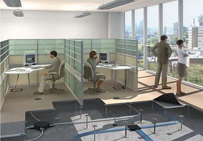
This project consists of several office towers, each with multiple floors, and each floor “divided” in half with the installation of an underfloor plenum divider. This separates the floor into a north half and a south half, each served by a respective dual path air handling unit.
The dual path air handling unit is best described as one unit comprised of two fan systems: in this case, an overhead multizone fan section and an underfloor fan section (see Figure 1).
Figure 1: Dual Path AHU Detail
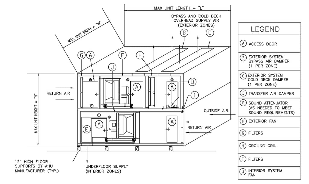
The overhead fan system is a multi-zone configuration with four total zones at each air handling unit. Each zone is equipped with an airflow monitoring station that sends a signal back to the air handling unit to open or close the associated zone cold deck or neutral deck dampers to meet the required airflow setpoints. The chilled water coil is only located in this overhead fan system. These zones serve only the perimeter of the building and a temperature sensor at each zone perimeter determines how much cold deck or neutral deck airflow is supplied to the zone.
The underfloor fan system provides discharge air in a range from 62°F to 68°F based on the room temperature of the open office space the system serves. A transfer air damper is installed in the cold deck zone of the overhead fan system that modulates open and closed to meet the discharge air temperature setpoint of the underfloor fan system.
There are approximately 130 to 180 floor diffusers (depending on the location) served by each underfloor fan section, which equates to between 260 and 360 diffusers for the entire floor. The underfloor airflow is transmitted from the mechanical room underneath the raised access floor tiles through a series of duct socks. Although the Design Team did not specify a design airflow for each floor diffuser, it is crucial that there are no ‘dead’ spots when measuring the airflow at each diffuser. In fact, the purpose of the duct socks is to equally distribute the airflow throughout the underfloor to prevent any dead spots from occurring.
Overhead and Underfloor Multizone Fan System Testing
Testing and balancing the overhead multizone fan system was very similar to most multi-zone units. Pitot tube traverses and flow hood readings were obtained to ensure that airflow setpoints were being met and all airflow monitoring stations were correctly calibrated.
Testing the underfloor fan system, however, was substantially more difficult due to the lack of any traverse opportunities. In this situation, it was crucial to communicate with the Mechanical Contractor to make some modifications to a sample underfloor system that would provide a testing method that could be repeated with other air handling units. By design, the duct socks only attached to a small hard duct transfer at the mechanical room wall underfloor. We coordinated with the Mechanical Contractor to install 8’ long hard duct transfers at one air handling unit which provided Pitot tube traverse locations for testing airflow. Because of this modification, our team was able to consistently develop a total supply airflow for the fan and correlate the results to a velocity readout at the back of the unit on the return air side.
The second challenge with the dual path air handling units that had to be addressed was a method for determining the airflow that transfers from the cold deck of the overhead fan system to the intake of the underfloor fan system. The overhead supply fan capacity was sized to provide the design airflow to all perimeter zones plus an extra 20% through the transfer damper to allow for proper cooling of the underfloor fan system. Therefore, determining the airflow through the transfer damper was important to testing the total capacity of the overhead supply fan.
When looking at the airflow temperatures of the system, it became clear that a reliable method that could be used was a temperature analysis of the underfloor supply airflow:
Typical temperatures that were recorded:
- Return air temperature (RAT): 70°F
- Cold deck temperature (CDT): 50°F
- Supply air temperature (SAT): 62°F – 68°F
The transfer airflow (TAF) could be obtained by the equation: %TAF=(RAT-SAT)(RAT-CDT)x 100
Understanding that using a velocity readout at the return air side of a unit and a temperature analysis to measure and record fan airflow capacities has some expected standard deviation errors, we brought the Design Team into the conversation about these testing methods. A discussion and explanation of our testing methods were presented to the Design Team, which led to a complete agreement on the testing procedures and the data that would be collected and reported.
System Challenges and Lessons Learned
While testing and monitoring the underfloor system, there were three challenges that were identified and noted:
- There was a noticeable 5°F to 8°F temperature gradient in the underfloor supply air temperature as the distance from the AHU to the exterior perimeter increased.
- The underfloor supply fan was designed to control to a 0.06” WC static pressure. Maintaining this level of accuracy at the static pressure sensor was critical for the system to operate properly.
- Demountable walls were constructed to create special offices and meeting rooms at the perimeters of the floors. These rooms had the potential to have short term/high demand loads that would require a substantial increase in airflow to maintain comfort conditions.
The first challenge observed was a change in underfloor supply air temperature that increased as the distance from the supply fan increased. It was essential to verify that underfloor leakage was not the contributing factor to this temperature gradient. As we prepared for testing of each system, routine underfloor inspections were made to ensure that penetrations were being sealed properly. Our testing results indicated that the velocity traverse at the AHU routinely matched the underfloor airflow readout of the sum of all floor diffusers. It was concluded that this temperature gradient was a result of the heat load provided by electrical devices installed underfloor as well as perimeter heat loads at the exterior skin of the building. Additionally, the temperature gradient was noted to be larger during periods of higher outside temperatures and where the sun might be directly shining on the exterior perimeter of the building.
The second challenge was the ability of the control system to maintain a small static pressure setpoint within the underfloor plenum. If a Controls Contractor uses a ±1.00” WC pressure transducer in this application, there will be issues with controllability of the setpoints. As a result, conversations were had with the contractors to highlight the importance of using transducers that would be capable of accurately measuring small variations in static pressure. While testing the system, static pressure discrepancies and issues would be easily detected by monitoring fan speed. The most common issue observed was to see the fan speed operating at minimum with an underfloor static pressure greater than the setpoint. Common issues were cut/damaged poly tubing, incorrectly scaled pressure transducers, and improper reference locations.
The last challenge observed with the underfloor distribution system was the occupants use of the space. Demountable walls were constructed throughout the office floor plans to create huddle rooms, conference rooms and meeting rooms. After the building became occupied, it was common to observe many more people within a room than expected. As a result, because the underfloor distribution operates as one large system, the thermostat could not direct more airflow into the space similar to a traditional VAV system. This challenge, combined with the temperature gradient observations noted above, produced several zones that were prone to hot calls and an inability to maintain comfort conditions.
Many of these challenges had to be addressed with the control contractor. Time was allotted to trend space temperatures, underfloor temperatures, fan speeds, damper positions, etc. After observing the trend data, test and balance technicians took the time to provide suggestions to temperature reset schedules that could overcome some of these challenges. As a result, the Design and Construction Teams became aware of the dynamic loads and the ability to work within the limitations of the underfloor distribution system.
Conclusion
In a system such as the one described in this article, the test and balance technician must get creative to develop testing methods and gather all the necessary flow measurements. Notably, the most important aspect when faced with a unique system is constant communication with the Design Team, Construction Team and Owners to ensure that everyone understands the system performance.
Written By George Teasdale, P.E.