“A sum can be put right: but only by going back till you find the error and working it afresh from that point, never by simply going on.” – C.S. Lewis
During a recent project at University of Texas Medical District in Galveston some unique fan performance issues were discovered. The fans in question were constructed of stainless steel as required by the Owner because of environmental hazards due to the location. The fan system consisted of two direct drive fans with independent high plume stacks. There were isolation dampers on the inlets of the fans as well as a bypass damper to allow for the desired sequence of operation. During initial testing of the associated exhaust terminal units both fans operated continuously as per the Owner’s requested sequence. It was only after all pressure dependent devices were calibrated and fan testing was started that performance issues became obvious. All further testing was conducted with only a single fan operating due to the critical nature of providing true redundancy of the system.
Fan Performance Troubleshooting
The first set of data that indicated that we had a fan performance issue was taken by traversing the inlets of both fans independently. When these measurements were taken, the first thing that stood out was the lack of static pressure in the duct. The fan was rated for 3.9” SP and 25,000 CFM at 1070 RPM adjusted for the local density. With this design data in mind it was troubling that the fan inlet static was only -2.0” SP with a discharge pressure of +0.10” SP, resulting in an airflow of only 23,065 CFM, which left several air valves significantly below design airflow. This airflow measurement was verified in multiple locations to ensure accuracy.
Once this deficiency was found and discussed with the Owner and design group, several suggestions were made to attempt to resolve the issue. The first suggestion was to increase the fan operating speed from the design point to the maximum speed of the fan. The design point called for 1070 RPM, or 55Hz, on the associated VFD. This suggestion did not address the fact that the fan was not operating on the provided fan curve (See Figure 1). We suggested it be considered that there was a problem with the fan, but in the interest of quickly resolving the issue it was decided to increase the speed and see if that would resolve the problem. With input from the fan manufacturer and vendor, the maximum frequency limits on the VFDs were increased to 67Hz. Additionally, the vendor representative inspected the inlet cone to fan wheel gap. While this gap was slightly higher than design it was within the acceptable operating range for the fan. The resulting operating point with the fan operating at 67Hz was 24,145 CFM at 2.9” SP. Unfortunately, this did not provide adequate capacity or match the curve for the fan.
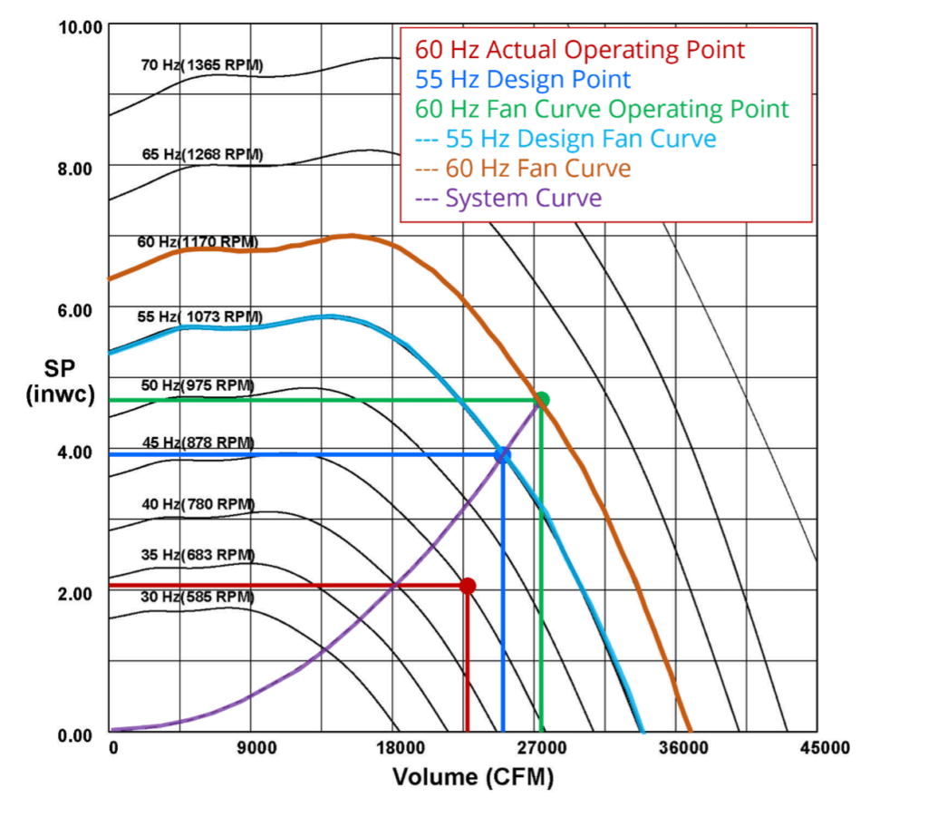
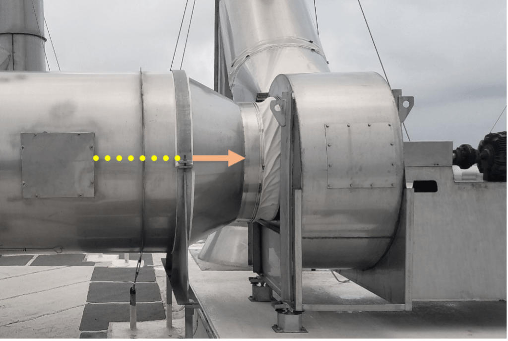
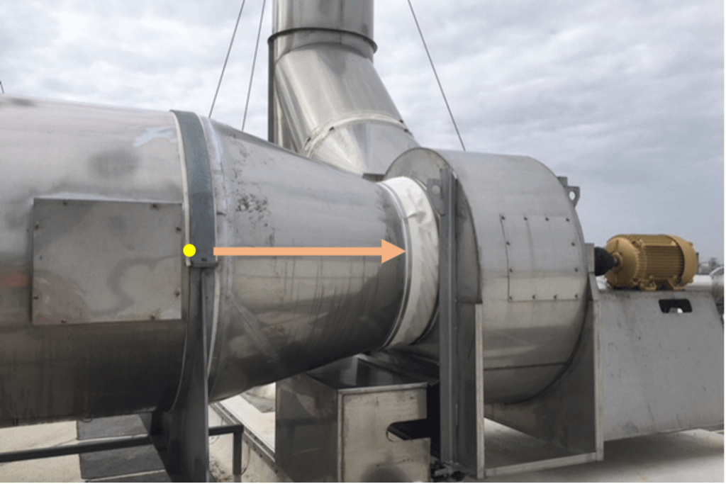
At this time, it was agreed that the fan was not operating on the fan curve, but it was the opinion of the manufacturer that it was system effect – not the fan. The next option chosen to pursue was the possibility of reducing the inlet system effect that was believed to be affecting the system capacity. The fan inlets were within the SMACNA limits for duct construction; however, they did not conform to the manufacturer’s installation guidelines of 15˚ maximum transition angle for converging duct diameter inlet. This required the inlet reducer to be modified to conform to the maximum angle listed by the manufacturer. The reducer was installed between the 60” main duct and the 40” fan inlet diameter. Once completed, the fan was retested with the fan still operating at the increased speed previously set. Figure 2 shows one of the fans before the transition was replaced and Figures 3 and 4 show the same fan after the longer transition was installed. Unfortunately, this resulted in a negligible amount of additional airflow and static pressure.
Examining the Ventilation Equipment
Due to the unsuccessful nature of the two efforts detailed above, we prompted the Owner to inquire about the AMCA certification of the fans in question. The submittal data provided to the project included a fan curve indicating the provided fan would provide the anticipated capacity. There were many conversations comparing the material properties of steel and stainless steel. The concern primarily centered around the fact that the AMCA certified fan was made of carbon steel and the difference in construction between it and the stainless steel fans installed. While the manufacturer insisted that these changes could not possibly affect the performance, we remained unconvinced. The removal of one of the fans for testing was allowed to expedite getting a temporary replacement unit that was factory tested sent to the job site. The first reason was to compare the performance of a known fan on this system and allow the Owner to maintain the design airflow and the stainless steel fan was for testing purposes.
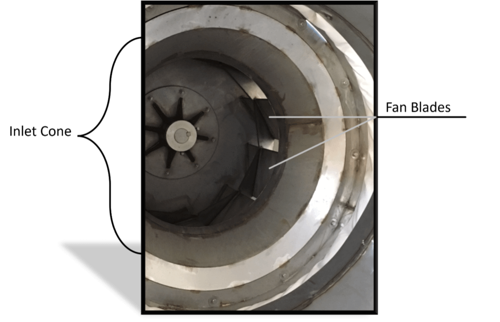
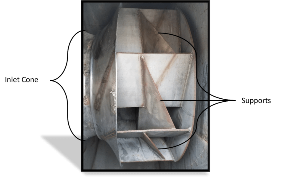
To expedite the process the Owner allowed the test fan provided to made of aluminum, which gave the manufacturer the ability to prove the claim that it was a system design issue. Once the new fan was on the Roof, it was tested at the same speed with the identical building load as the previous fans. To our relief the new fan provided the design airflow and static pressure required for the project. It was at this time that our curiosity was peaked with the desire to know why the original stainless steel fan did not perform. Was it due to additional structural support required in a stainless steel fan or something else? (Figure 5) To achieve this, the stainless steel fan was removed from the Roof and sent back to the factory for AMCA chamber testing. At the end of testing we were notified that the inlet cone of the fan was not manufactured per the fan design. For this reason, the inlet cone of the fan wheel was the culprit for the loss of efficiency and performance.
This result was not expected as we had become convinced that the additional gussets on the fan wheel were the root cause. Due to the higher material strength of carbon steel these would not have been included in the AMCA tested fan. Once the root cause was identified and the original fan was repaired in the factory, we insisted that it be tested in the manufacturer’s approved AMCA chamber before returning it to the field. This was witnessed by the Owner, engineer and EAB due to the high level of interest in this being successful. Afterwards, the fan was returned to the project, installed and tested.
Article was written by Neil Redford.