
Over the last decade fan array systems have become increasingly commonplace in our industry. While fan arrays can provide numerous benefits over traditional AHUs there are several items that are often overlooked during the startup phase of each project. These items are key to proper setup and operation for fan array systems.
Fan Array Systems Fundamentals
- Inlet backdraft dampers should be checked for proper operation on each fan. Damper blades should be inspected for each fan to ensure an airtight seal at the inlet of each fan and free movement throughout the process of opening and closing. The damper must be able to close when a fan is not in operation. Ensuring each inlet backdraft damper can close fully and provide a seal prevents short cycling (recirculation inside the unit).
- Every fan needs to be checked for proper rotation, amperage, and RPM. Each fan should be treated with the same respect as an AHU with a single fan. Improper rotation on a few fans is a common place issue found in the field.
- Direct drive fans may need to operate above 60.0 HZ to achieve the design RPM. With direct drive fans, proper variable frequency drive (VFD) setup is crucial. Traditional setup of VFDs usually has the upper limit set for 60.0 HZ. If a fan array system is picked for a design RPM greater than the motor nameplate RPM, the drive must be setup accordingly.
- If the system is setup for a N+1 or greater redundancy, a system test in fan failure mode is necessary. Proving that the system can operate under an N+1 or greater scenario is key to proving fan performance and should not be overlooked.
- Worst case fan operation should be considered when drives are setup. If a system has a N+1 or greater condition listed in the submittal. The worst case operating scenario will drive the limits of the VFD.
VFD

From a TAB perspective these key items are often overlooked at startup and must be addressed later during the project. The most common issue is often with the VFD drive setup. If the TAB agency is involved early on and is present during startup these issues can be resolved. The typical manufacturer submittal data for most fan array systems will provide a fan curve for two different operating scenarios. The first is with all fans in normal operation and the second is for a fan failure mode. The fan failure mode will show an increased fan RPM and may even show a design hertz value. This RPM should be looked at as the worst case operating scenario for the fan array system. The design hertz listed in the submittal data can be used as guideline but is not a definitive answer to the necessary upper limit for the drive. Submittal data will often list a certain RPM motor and the motor nameplate RPM may vary due to limitations or motor availability at the time the AHU is manufactured.


For example, Figure 1 shows submittal data for a 1770 RPM motor to be used for each direct drive fan. Figure 2 shows operating Condition 1 is a full cooling scenario with all fans in operation with the fans operating at 1963 RPM and 66.5 HZ. Figure 2 also shows Operating Condition 1 with a failed fan in a full cooling scenario listed with three of the four fans operating at 2237 RPM and 75.8 HZ. In this specific example the installed motors that came with the AHU were noted to have a nameplate of 1750 RPM. With this difference in motor nameplate RPM the operating hertz for each scenario will be different from the data listed in the submittal.
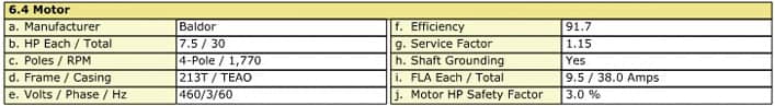
Figure 1
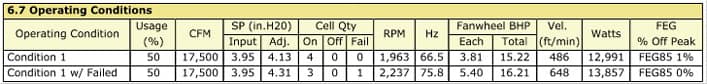
Figure 2
Using the formula below, the required hertz for Condition 1 with a failed fan would be our worst case scenario and would require an increase in the operating hertz to 76.7 HZ to achieve the design RPM.
(Design Operating RPM / Motor Nameplate RPM) x Motor Nameplate HZ = Operating HZ
In this specific scenario the resulting conditions required an increase in the VFD maximum hertz. The nameplate RPM of the motor should always be checked and adjusted for during the startup of any AHU. The same can also be true in reverse. Say, in our specific example, the installed motors had a nameplate of 2250 RPM; this would further change the setup of the drives as operating above 60.0 HZ would no longer be necessary. Keep these things in mind during startup and the testing phases of fan arrays to ensure proper equipment operation.
Written by EAB teammate, Durwood Lassiter, III.