In a recent project, we were tasked with balancing a heating water system with 100 coils. The coils were serving air handling units, fan and coil units, computer room air conditioning units, and terminal units. The building heating water system was equipped with two boilers, two pumps with variable frequency drives (VFD) controlling the system differential pressure, and a Tour & Andersson (TA) (Victaulic) balancing valve installed at each respective coil. The system was designed to solely use the TA valve differential pressure ports for balancing purposes. Major equipment was not equipped with coil entering and leaving test ports, only the terminal unit reheat coils had test ports but were not used because of low design pressure drop and flow.
Heating Water System Test and Balance
We approached the balance by first presetting the TA balancing valve to 1.0 on the dial to all terminal unit reheat coils with a design pressure drop below 0.75’ WC. The idea was not to set the TA valve below the 1.0 setting to prevent future debris buildup that could create a blockage to flow. These ¾” valves accounted for 65 coils and the remaining 35 valves ranging from ¾” to 2-½” were set to the full open position.
The pump shutoff head was confirmed and verified to match the manufacturer pump curve. The pump total flow was set and initial coils readout was obtained and confirmed to match the pump flow. The next step was to set the design flow at each full open valve using the TA balancing wheel to determine the relationship between flow, pressure drop, and associated valve sizes. Starting with valves on branches that were closest to the pumping system and have higher flow than design. We throttled down a group of valves with higher flow in hopes of gaining flow to the lower ones. Surprisingly, the lower flow ones hardly gained anything! We immediately turned to the product submittal data information and discovered a group of 13 valves were undersized. The number of outstanding valves seemed to be negligible for the heating water system, but the environment they served was considered a critical space.
Balancing Valve Selection
The project team was informed of the situation, but the mechanical contractor refused to accept the fact that those valves were incorrectly selected and installed. The contractor said all balancing valves were installed in relation to the coil pipe size and were selected within the minimum and maximum flow rates. Unfortunately, the product manufacturer has fine print showing the opposite of the contractor’s statement, as follows:
Balancing valves should be sized in accordance with the GPM flows and not in relation to pipeline size. Sizing valves based on the minimum and maximum flow rates is not recommended. Valves should be sized using the nominal flow rates only.
Figure 1 – Manufacturer Valve Selection Guide
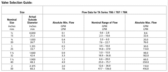
It is essential that the contractor understands the difference between the nominal flow rate in relation to the internal design of the valve or to match them with the pipeline size. According to Figure 1, a 14 GPM rated coil would have been selected as a 1-¼” nominal valve size; however, the contractor installed a 3/4” valve to match the equipment coil pipeline fitting at 3/4”. With a 1-¼” nominal valve size selected for replacement, the pipeline fitting would have to be transitioned from ¾” to 1-1/4”. Any mishap in selecting valves can have significant impact on the deliverable timeline and costs for the project. Due to the critical spaces the HVAC equipment served, project schedule constraints, and the lead time of the available valve sizes only three out of thirteen undersized valves were upsized and replaced. The test and balance technicians were then instructed to rebalance the system. After all coil flows were set, the remaining ten undersized valves still did not meet the design flow, as expected.
There were a couple of things noted during that balance. First, we could not further throttle the 65 coils with ¾” valves installed that had a design flow range from 0.5 to 2.0 GPM. These valves were considered oversized based on the manufacturer recommendation and had more flow than expected, even though the valve was set at a 1.0 throttled position. Second, the recorded flow for these 65 coils may not have been that precise because of the low flow conditions. With no other options available, the Engineer of Record (EOR) was brought in to help develop a solution to the balance. After thoroughly reviewing the current balancing methodology and data, the directive was given to add diversity to the system by randomly commanding 30 terminal unit control valves to a full closed position. With the diversity applied, the 10 undersized valves finally achieved their design flow. Once the rebalance was completed, the final differential pressure was recorded and input into the BAS system as a control setpoint for the pumping system.
The balanced condition contributed to a higher cost to operate the system at a higher DP; inversely, operating at a lower DP with the correct valve size installed and no added diversity would have had a lower long-term operating cost.
With the heating water system successfully balanced, the project team at once turned to the chilled water system where similar valve selections and installed conditions were again identified. Seventeen of the thirty-two valves were undersized and eventually, all seventeen were replaced and the chilled water system balance was brief.
Selecting balancing valves may not be part of the TAB scope and/or their specialty; however, TAB agents can develop a test plan, troubleshoot and identify system deficiencies, and work with the Design Team to deliver the most efficient total system balance.
Written by Thi Pham.