“Every problem has a solution. You just have to be creative enough to find it.” – Travis Kalanick
When walking up to any variable system to be commissioned, all functional test scripts that are written only include sequences. In my opinion, sequences are only a fraction of commissioning for certain systems. When performing functional testing, sequences are the easiest to pass or fail and document whether they are working or not. What really makes the difference between a variable system that performs versus a variable system that performs efficiently is the tuning process of the PID loops modulating the system.
Understanding the PID Control
As a CxA, I deal with many control contractor technicians. While discussing tuning PID control loops with them, it amazes me that a majority of control technicians do not know how to properly tune PID loops. This is mostly due to the misunderstanding of the Proportional, Integral and Derivative (PID) multipliers and how each one effects an output signal.
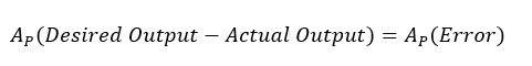
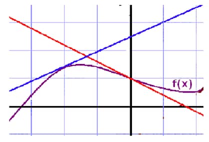
The proportional aspect of a PID loop calculates the error in real time. It takes the desired output and subtracts the actual output to get the present error between our output and what end result is attempting to be met. This error can then be multiplied by a coefficient to magnify the error to make the equation react faster. Too big of a multiplier and controlling too fast will have negative effects such as overshooting the desired output.
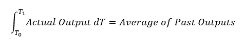
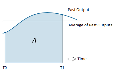
The integral aspect of a PID loop calculates the average of the past outputs. This gives the PID loop a stable base to control around once it reaches steady state control. When an output is at steady state, almost all of the output percentage will be calculated through the integral calculation. Having a large sample size of the past will not only steady the control output but will also slow down any major change in the proportional error. A negative effect of having too large of an integral sample rate is the lack of speed in which the output can control to impulses in a system.
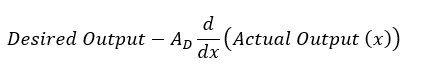
The derivative aspect of a PID loop calculates a predicted future error by using the approach of the control output to the desired output or setpoint. The derivative, if properly set up, will counteract a control output which is fast approaching the desired output. This assists the proportional gain from overshooting the desired control output. A negative aspect of having too big of an amplifier for the derivative can make a control function underdamped (sinusoidal output) or even uncontrollable. If this happens the output will never reach a steady state condition or the output will go to the maximum and back to the minimum output ratings of the control module output.
PID Loop Tuning
Part of controlling a variable HVAC system means having to deal with setpoints and equipment outputs that are constantly changing to better a system’s efficiency with respect to the building demand and outside air conditions. But what happens to the efficiency of the system when the PID loops controlling the outputs have not been properly set up? A good example of this scenario took place multiple times while commissioning cooling towers. If the cooling tower PID loop is set up to be underdamped, the fan will overcool the condenser water by ramping up to a high frequency too quickly. When the logic catches up, the fans are then lowered to allow the condenser water to raise back to setpoint. In some sequence of operations, if the temperature goes below the setpoint by a certain number of degrees the fans will be de-energized completely. These fans and the drives are very heavy, which takes even more electrical energy to change momentum from a complete stop. When a cooling tower fan is ramping up and down, the added electrical demand used to change the inertia of the fan blades, drive shaft and torque converter could be saved if the PID loop is tuned properly. This allows the blades to control to a constant speed and very little electrical energy is wasted by changing the inertia of the heavy mechanical parts.
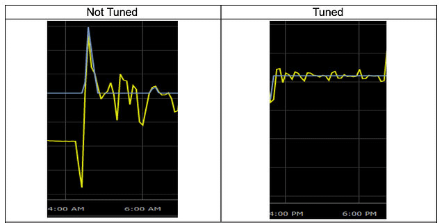
While monitoring a cooling tower VFD prior to tuning, it was observed that the amperage had a 15 Amp swing due to the fan motor speeding up and then ramping back down. The speed output would ramp 90% to 95%, over cool the condenser water, then the logic would turn off the Start/Stop of the fan motors. Once the PID loop was tuned, the cooling tower fan speed remained around 20% to 30% while the condenser water temperature remained ±0.2°F of setpoint.
The trend of the condenser water temperatures “not tuned” versus “tuned: are shown below:
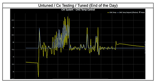
The “Untuned / Cx Testing / Tuned” graph shows the entire testing day. The beginning of the day (untuned) and what the tuning process can do for a condensing water system once the system is tuned. Even though this takes constant attention, the CxA could potentially save the client thousands of dollars due to the electrical efficiency gained by the tuning process.
Article was written by EAB team member, Jordan Ourso.