We had a recent opportunity to perform the testing and balancing in an ISO 7 cleanroom envelope that involved setting up a pressure cascade of 17 rooms with 550 fan filter units (FFU). This project provided various challenges that were solved through team communication and extensive testing.
Cleanroom Testing
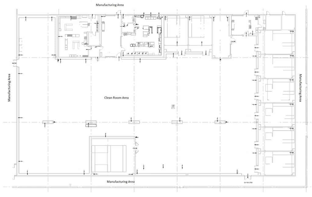
The cleanroom was located within a manufacturing facility with large open bay doors designed for loading and unloading material that would be opened periodically and closed throughout the day. Although there was an ante room located within the cleanroom envelope that served as a buffer for an office, the envelope as a whole was not buffered from the expected pressure changes of the manufacturing facility. Below is a layout of the envelope nested in the manufacturing area.
Adding another variable to the building pressure surrounding the cleanroom, the manufacturing area was served by two rooftop units (RTU) that relied on barometric relief dampers when the units entered an economizer mode. Since this method of building pressure control is not precise, we had concerns that maintaining the correct pressure relationship between the cleanroom envelope and the manufacturing area would be challenging.
HVAC Plenum Design
Finally, the cleanroom spaces were designed to be served by three RTUs, each serving the large common room in the center of the envelope and the associated rooms adjacent to the center. The units would supply variable volume terminal boxes above the ceiling into a recirculation plenum driven by the FFUs. The return airflow was provided by low return grilles in the recirculation plenum walls. Because the units were designed to be variable volume and the three units served a common area, we had additional concerns about maintaining the proper pressure cascades within the cleanroom as supply boxes modulated open and closed.
As we began testing and balancing the systems, we spent a significant amount of time communicating and explaining our concerns with maintaining proper pressurization of the space with the Design Team, Construction Team and Commissioning Team. As a result of the meetings and conversations the following design changes were implemented:
- The supply VAV boxes serving the cleanroom envelope were changed to constant volume.
- The each of the room pressure sensors were changed to reference the large center cleanroom instead of the manufacturing space. Only the large center cleanroom pressure sensor would reference the manufacturing corridor.
- The return fan at the RTUs was changed to be constant volume instead of modulating to maintain room pressure setpoint. This prevented a unit from modulating each time a door was opened and affecting the other two units serving the same area and causing pressure hunting problems.
 Clean Room Pressure
Another challenge that our team ran across was the amount of outside air designed to pressurize the cleanroom space proved to over pressurize. The target center cleanroom pressure was +0.05” WC; however, our testing showed that with the units operating at the designed outside airflow rate, the cleanroom pressure would measure +0.18” WC.
As a result, we explained the results to the design team and requested the minimum outside airflow ventilation rate for each of the units. We received the following information:
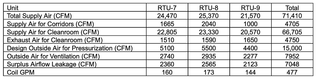
Adjusting the outside airflow from the “Design for Pressurization” column, down to the “For Ventilation” column still produced a cleanroom pressure that measured +0.10” WC. To solve this issue, the units would have to operate in a relief mode so that the space could still receive the minimum outside airflow required for ventilation and achieve the required room pressure of 0.05” WC. The final adjustment of the system resulted in a total outside air volume of 8000 CFM into the cleanroom envelope and with a measured 3300 CFM of relief air.
Additional testing was performed to see how the cleanroom envelope would react to experiencing the manufacturing area pressurization variables. Our team performed baseline readings of the cleanroom envelope with the manufacturing area bay doors in the closed position. The cleanroom envelope pressurization was then measured with the manufacturing area commanded into an economizer mode, and then again with the bay doors in an open position. The results of the test indicated that the cleanroom envelope would experience a variable pressure fluctuation no more than ±0.015” WC at any given room in either of the modes. These results were presented to the design team were noted to be acceptable.
Testing cleanroom envelopes can be quite challenging because the operation of the facility depends on the equipment to function very precisely. Communication with the client and design teams are critical to the success of the project when additional challenges get presented.
Written by George Teasdale, P.E.