On a recent project, HVAC Air Balancing was performed on a cleanroom for a manufacturing process facility. A unique challenge was presented when the room pressures from the cleanroom suite did not cascade properly after all supply, return and exhaust airflows had been set to the design airflows.
Cleanroom Airflow Design
The cleanroom suite consisted of a single roof top unit (RTU) serving nine constant volume supply air terminal boxes with electric reheat. Each of the terminal boxes provided supply airflow above the ceilings within each room, and approximately 110 fan filter units distributed the airflow through HEPA filters into the rooms. The return air path for the RTU utilized a return wall system with common low wall plenum return grilles. The RTU return ductwork was routed within the wall plenum of each room. The room air change requirements were met by the fan filter units; therefore, any return airflow that did not make its way back to the RTU was recirculated through the common return wall and into the above ceiling plenum. Two exhaust fans were installed with exhaust taps open above the ceiling for future tool hook ups.
HVAC Air Balancing in a Critical Environment
After all supply, return and exhaust airflows were balanced to the design values and the fan filter units were verified to be operating at design airflow, the room pressure cascade testing was performed. TAB technicians that have spent much performing HVAC Air Balancing in critical environment rooms know that making minor adjustments to the airflows within a room may be necessary due to numerous factors that contribute to critical room pressures. These factors can be due to the construction quality of the space above and below ceiling, door undercuts, surrounding building pressure, etc. Similarly for this project, the room pressurization did not meet the design requirements and airflow adjustments had to be made.
Using the return ductwork dampers located in the return ducts serving the wall return plenum, the dampers were adjusted as necessary to bring each room into the required pressure range. Our team did, however, struggle to find the correct airflow adjustments that would achieve the required room pressure relationship from the Anteroom to the Materials Movement Corridor.
During the adjustment process, one of our team members noticed that the pressure relationship issue was immediately solved when a ceiling tile was opened while looking for a volume damper. Since the above ceiling space is the return pathway to the FFUs, we began to inspect the 18” x 18” low wall return grille to see if this could be a restriction point for the airflow which got relieved when the ceiling tile was opened. By design, the amount of airflow that would need to be recirculated to the FFUs and returned to the RTU was 2205 CFM within this Anteroom. Clearly, the single 18” x 18” return grille was too restrictive.
Our team brought the general contractor, mechanical contractor and design engineer into the space to discuss our testing results and what we were seeing with room pressures. We demonstrated the pressure “bottle-neck” that was occurring at the Anteroom and how it was caused by the restrictive return/recirculation pathway. We further demonstrated by opening a ceiling tile only enough that a 6” x 48” (24” x 48” ceiling tiles) gap would relieve the room pressure and allow the entire cleanroom suite pressure cascade to flow properly.
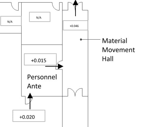
It was determined from the demonstration that the mechanical contractor would increase the return grille size from an 18” x 18” to a 28” x 28”. The installation was completed two weeks later and the pressure cascade was functioning properly as indicated in Figure 1.
Figure 1 – Properly Functioning Pressure Cascade
Written by George Teasdale, P.E.