Hoistway and stairwell pressurization systems often present unique and challenging circumstances for TAB firms. A recent 15-story hospital bed-tower presented its own set of challenges with the hoistway and stairwell pressurization systems.
To begin let’s describe the systems involved in the testing:
- For Levels 4 – 12, each floor is served by an air handling unit (AHU). The outside air for each floor is pre-treated and provided to the AHU by a manifolded dedicated outside air system (DOAS). The general exhaust air for each floor is also served by the manifolded DOAS. A set of isolation exhaust fans (IEFS) serves the isolation room exhaust air.
- Level 3 is served by four AHUs and each AHU is provided pre-treated outside air from a DOAS. The general exhaust air is served by a DOAS, and the isolation exhaust air is served by two separate sets of IEFS.
- Level 2 is a mechanical space and is served by smaller AHUs, fan and coil units (FCU), computer room air conditioning units (CRAC). There is no exhaust air on this floor.
- Level 1 and the Ground Floor are served by three AHUs and each AHU is provided pre-treated outside air from a DOAS. The general exhaust air is served by a DOAS, and the isolation exhaust air is served by a set of IEFS.
- The Basement is served by a single AHU with untreated outside air, general exhaust served by a DOAS, and smaller exhaust fans that provide exhaust to ancillary spaces such as mechanical rooms.
The sequence of operations for an event triggering the hoistway or stairwell pressurization systems did not disable the AHU, DOAS, or IEFS unless smoke was detected inside of the duct of one of those systems. To properly test the hoistway and stairwell pressurization systems we first needed to ensure all other systems had been tested and balanced to the design values and are operating in a stable and repeatable condition. This allows for the pressurization of each floor to be at the design offset per the mechanical plans and schedules. With all the pre-requisite testing completed, testing of the individual components of the pressurization system could begin. The total plan outside air value of the tower is 108,425 CFM and the plan exhaust air value of the tower is 81,335 CFM providing a differential of 27,090 CFM of positive ventilation. The building pressurization measured on the Basement floor was noted to be operating at +0.017” WC.
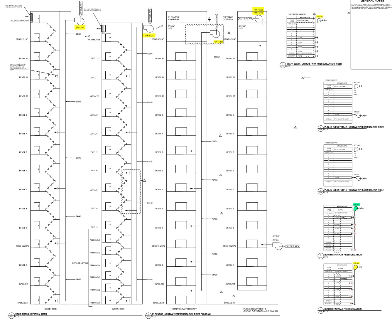
The pressurization systems are as follows. SPF-1301 provides pressurization to Stairwell 2 at a design value of 28,000 CFM and modulates to maintain a differential pressure setpoint as sensed on Level 1. Stairwell 2 serves from Level 15 to the Basement of the hospital bed tower and modulates to maintain a differential pressure setpoint as sensed on Level 1. SPF-1302 provides pressurization to Stairwell 3 at a design value of 45,000 CFM and modulates to maintain a differential pressure as sensed on Level 1. Stairwell 3 serves from Level 14 to Level B2 of the parking garage. HPF-1301 provides pressurization to the service car elevator bank serving Level 14 through the Basement at a design value of 44,000 CFM. HPF-1302 and HPF-202 provide pressurization to the 3-Car Passenger Elevator Bank with a total design volume of 20,000 CFM. HPF-1303 and HPF-201 provide pressurization to the 2-Car Passenger Elevator Bank with a total design volume of 26,940 CFM. Each fan was proportionally balanced and tested to provide design airflow. The total design volume of all fans operating was noted to be 163,940 CFM.
With all fans set to achieve the design values we began testing the hoistway pressures and stairwell pressures. The stairwell pressures and door pulls were found to be within an acceptable range and the pressure setpoint was able to be set. Then came the testing of the hoistway pressures. With the service car fan operating at the design CFM values, the service car hoistway pressures were found to range from +0.015” WC to +0.055” WC. With the passenger car elevator fans operating at the design airflow values the passenger car hoistway pressures were noted to range from +0.045” WC to +0.145” WC. The required differential pressure for each hoistway is +0.10” WC to +0.25” WC. With the system not achieving the design pressure requirements and the fans reverified as providing the design air volume, we began to look at the possible solutions. Our worst-case scenario was that all stairwell and hoistway fans were operating at simulating an event in all of the smoke compartments at the same time. With the building operating in this condition, we then measured the differential pressure at the loading dock on the Basement floor and noted the pressure to +0.13” WC. The data was then recorded and forwarded on to the Design Team and another test scheduled with the General Contractor, Mechanical Contractor, Mechanical Engineer of Record, and the Fire Protection Engineer of Record.
All parties returned to retest this system the next day. The results were consistent with the previous test. The fire alarm protection engineer and mechanical engineer recommended some new design air values at the air injection points for the hoistways and stairwells. The fire alarm protection engineer also recommended re-sealing of the elevator hoistways as part of his visit. We agreed to retest after the sealing and rebalancing of injection points was completed. On the next test similar results were found and the pressures did not achieve the design values. With all data indicating we were hitting the design airflow values and the fire model indicating we should be achieving the design pressures, we began looking for the solution.
The overall building pressure was an issue, being +0.127” WC. With all pressurization fans in operation, we were operating at a positive 191,030 CFM. In normal operation the building operates at 27,090 CFM. Working with the Design Team, General Contractor and Mechanical Contractor we began experimenting to narrow down the issue. We started by measuring the pressure of the service car elevator on the floor that had achieved the worst pressure. The recorded pressure was a +0.043” WC. To experiment and see if relief would help, we propped open the door to the mechanical room and opened the access door in the mechanical room relief plenum. The resulting pressure at the elevator bank was noted to be +0.145” WC. We then measured pressure on another floor and found an improvement under these conditions. Continuing the experiment, we proceeded to simulate this condition all the way to Level 12. The resulting pressures on those floors under this scenario were all passing. Levels 3 through the Basement were noted to not have a clear path of mechanical or barometric relief and were noted to not pass under these conditions. With this data in hand the design team elected to add a louvered opening with fire damper and barometric relief damper on Levels 4 through 12 and a retest was scheduled.
It was determined that Levels 4 through 12 were able to achieve the required pressures. Level 3 through the Basement still had failing values at this test. Using this data, the Design Team elected to add means of mechanical relief on Level 1 and Level 3 by adding relief fans. On Level 2 and the Basement, the Design Team elected to add barometric relief and fire dampers to relieve the pressurization. The fans were then procured and tested to provide their design values. Another test was then scheduled for a final pre-test of the system.
During the final pre-test, we began by testing all systems and recording the data and found the passenger car elevator banks were still having issues achieving pressures. It was noted that the General Contractor had added adjustable door bottoms to the passenger car elevator lobby at the direction of the Fire Marshal. The undercuts on the doors had been noted to exceed 0.75”. Experimenting continued and we found that the door bottoms were causing the Elevator Lobby itself to pressurize making it difficult to achieve the required design pressure. The door bottoms were then adjusted by the General Contractor to the maximum height of 0.75” and testing continued. With some fine tuning of the differential pressure setpoints and fan speeds we were able to achieve the required pressures. The tests were repeated under all possible conditions that could arise with the pressurization systems. All systems were then able to achieve the required differential pressure requirements and door pulls.
In conclusion, this was an interesting and uncommon problem to encounter with hoistway and stairwell systems. Typically, in testing hoistways and stairwell systems leakage is found to be the main problem. In this instance we needed to introduce a means for building relief. Working closely with all parties involved – the Owner, Architect, Mechanical Engineer, Fire Protection Engineer, General Contractor and Mechanical Contractor – resulted in a repeatable test result that met all requirements. Having great Construction and Design Teams that are willing to work through issues were key to providing a quality product to the Owner.
Written by Durwood Lassiter III, TBE.