“Do what is right. Not what is easy.”
– Roy T. Bennett
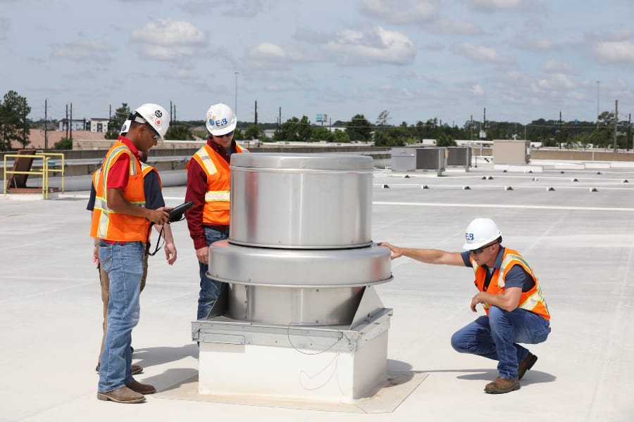
EAB San Antonio worked on a project for a medical facility created from the renovation of an existing building. The building had previously been balanced by another contractor but was experiencing pressurization issues with infiltration above the ceiling. The infiltration caused condensation on the supply ducts and diffusers, which resulted in damage to the ceiling. The facility was provided with new rooftop air handling units with VAV boxes, ducted return air, an outside air intake hood with an airflow measuring station and constant volume exhaust fans.
HVAC Air Flow Problems
Our initial inspection found that the exterior walls were open above the ceiling to the outside soffits. This was an existing condition that the construction plan did not address. The General Contractor later attempted to seal the areas with mixed results due to accessibility. We also found that the outside airflow monitors were not operational. The original test and balance contractor was brought back in to balance the outside air.
However, the problems continued so EAB was brought in to further investigate. Additional testing indicated that the outside airflow monitors were not calibrated. The programmed operating ranges, sizes and flow coefficients for the outside airflow monitors were found to be incorrect. Additionally, the return system had not been balanced.
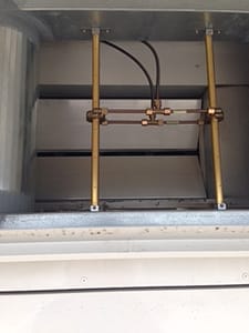
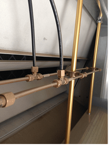
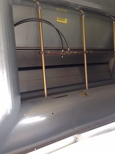
The outside airflow monitors were installed in the outside air opening. A rain hood was mounted over the opening which caused the outside air to be drawn in from below the opening and forced to turn before entering the monitor. In all cases, the sensing tubes were the full height of the hood and were installed in close proximity to the control dampers. Under these conditions, either 1/3 or 1/2 of the sensing ports were above the air path into the unit (See Figures 1 and 2). The other sensing ports would be affected by the control damper blade positions. In Figure 3 it is shown that the damper section is larger than the outside air opening and the sensing tubes are offset to one side. If the airflow measuring station was verified to read correctly under one condition (i.e., all boxes at maximum flow), then they would not be correct under other conditions (such as a change in outside air setpoint or reduction in supply fan speed). Both scenarios caused the control damper to move from the position and condition in which it was previously verified. Calibrating with the control dampers 100% open and airflow above setpoint and at setpoint resulted in different monitor readings when the system conditions changed and the dampers modulated.
RTU HVAC Installation
After discussing the issue with the air handling unit manufacturer representative it was indicated that they had been using this installation method for some time and never experienced an issue. Additional testing indicated individual velocities in the outside air sensing tube plane varied by as much as 63% from the average velocity. The difference between the highest and lowest velocities (excluding the occasional zero reading) was 381%.
Air Flow Balancing
In the end, the original TAB contractor returned to balance the return air system. Many areas with exterior exposures could be isolated from the rest of the building by closing doors. Some of these isolated areas were negative by the design exhaust to outside air ratio. At the direction of the engineer, exhaust fans were adjusted to reduce exhaust flows to the minimum required by code and outside air volumes were adjusted to prevent localized negative pressure issues. The outside airflow monitors were then calibrated with the systems in maximum flow operating conditions. Testing was performed to ensure that the facility would maintain a slightly positive pressure with the systems operating at minimum supply airflow.