A thorough review of drawings, submittal and an early inspection of equipment installation may identify issues that, if caught and corrected early, will make the process of turn over to the Owner use go smoothly and on time.
HVAC Inspection
On a recent project we were hired to test and record our findings on an air handling unit serving a renovated patient wing in a hospital. Two other TAB agencies had tested the unit and reported the unit total airflow as below design capacity. The AHU manufacturer had also inspected the unit twice.
A review of the previous TAB data submitted indicated the unit was operating well above the design RPM, with low total airflow leaving the unit and low fan total static pressure. The report also indicated the static pressure drop through the fan discharge cabinet was excessively higher than the submitted pressure drop. Neither TAB company provided information as to the cause of the low flow. The unit manufacturer stated that the ductwork connected to the unit was excessively restrictive. That statement was unjustifiable as the unit was reported to be low on airflow and static pressure.
The unit was a 100% outside air unit with an upper and lower stacked section. The air was preheated by a heating coil, pretreated by a heat wheel in a draw through configuration. The air was then forced through a cooling coil, through the lower half of the heat wheel, through a reheat coil and then into the supply ductwork.
Installation Inspection Findings
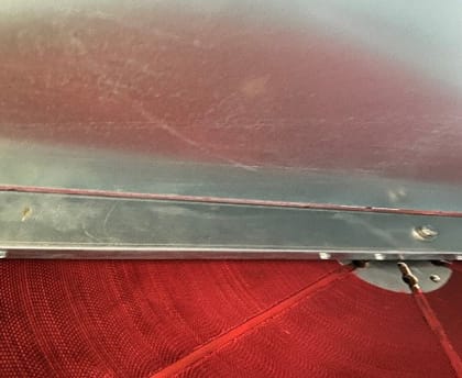
Upon inspection of the unit, our suspicions for potential issues were confirmed. Air was able to bypass both sides of the wheel from the positive side of the heat wheel to the negative side through a gap in the frame that was not related to the wheel sweep (See Figure 1).

Figure 1– Bypass at wheel
Additionally, air was also able to bypass the fan wall between the positive and negative sections of the fan through gaps where the fan wall connected to the unit casing (See Figure 2).

Figure 2 – Gap where fan wall connected to the unit casing
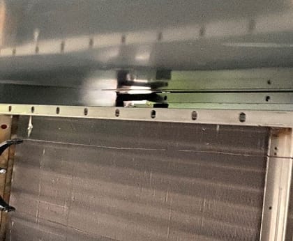
Figure 3 – Damage to cooling coil frame, allowing air to bypass the coil
Figure 4 – Damage to cooling coil frame
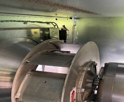
The frame of the fan motor was mounted in such a way that it had an impact on the air as it left the fan (See Figure 5). The unit submittal indicated the pressure drop through the discharge section of the unit was 0.01” WC. When operating at design airflow, we measured 0.85” WC across the opening.
Figure 5 – Fan motor mounting
Figure 6 – Opening from below with motor and motor mount obstructing the opening
Resolving AHU Installation Issues
After identifying potential air bypass areas, the mechanical contractor made temporary fixes using foam insulation and foil tape. The unit was designed to supply 3745 CFM at 6.043” WC and 89 Hz. All tests were performed with clean filters. Our initial test at 89 Hz showed the unit operating at 2715 CFM (72% of design). After sealing, the airflow at 89 Hz increased to 3525 CFM (94% of design). The GC then contacted the EOR and the mechanical contractor increased the fan speed to 96 Hz. The final test showed the unit operating at 3840 CFM (102.5% of design) at 5.5” WC of static.
While on this project, the manufacturer did not make any modifications to the unit set up. The unit was built and installed according to the submitted configuration. An early review of the submittal should have raised a question about the discharge section static. A lower fan discharge static would have allowed the fan to operate at a lower speed and allow for more filter loading. An early, thorough inspection of the unit installation could have found the internal issues of the unit and would have allowed for permanent corrections to be made. Early inspections by qualified, trained TAB contractors can save the Owner time and money and provide an optimally operating system, delivered on time, that all involved can be proud of.
Written by Kane Lassiter.


