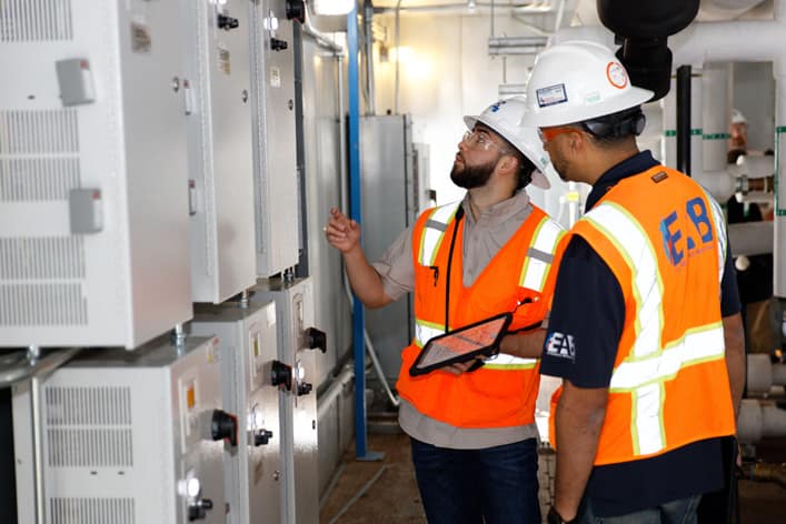
The purpose of this article is to provide an explanation of the emergency power testing during the electrical commissioning process of a new vivarium facility. Electrically, the building was designed to have two main power feeds to a “double ended” switchgear and a backup generator. Mechanically, the facility was served by two air handling units that were manifolded to a common supply duct serving several risers and all supply terminal units. All occupied areas of the building were served by these units.
Electrical Systems Design
The “A” feed to the switchgear served all the normal power distribution panels, the Life Safety ATS, ATS-LS, and one serving equipment loads, ATS-S2. The “B” feed to the switchgear served the other two ATSs which served the remainder of the equipment loads, ATS-S1 and ATS-S3. See the Electrical Riser Diagram below. The fire pump ATS was only connected to the two utility sources and not the backup generator.
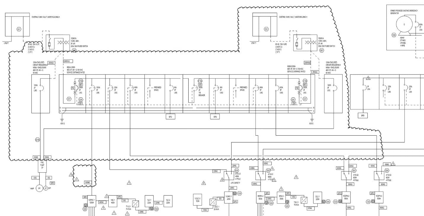
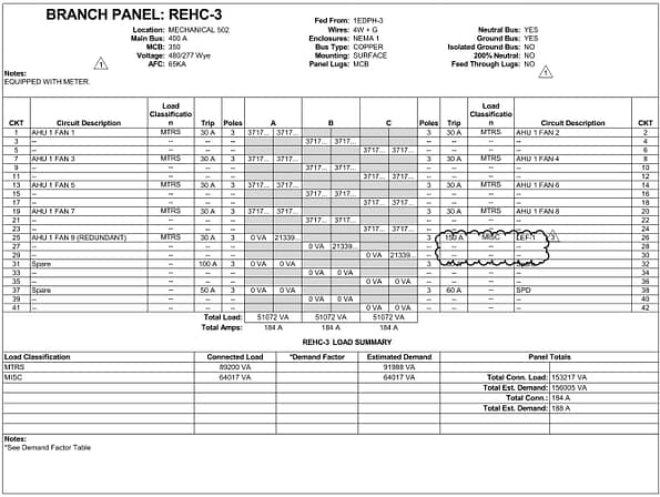
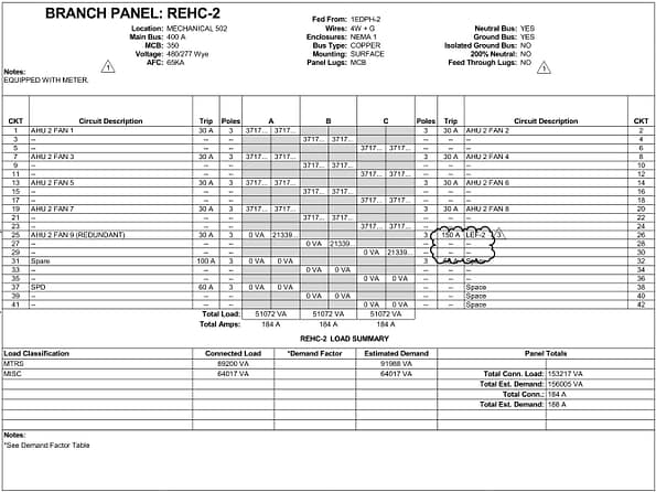
It was decided during the design phase of the project to split the service to the AHUs between the two power feeds. AHU-2 was fed from an emergency power panel on ATS-S2 which was on the “A” feed side of the switchgear. AHU-1 was fed from an emergency power panel on ATS-S3 on the “B” feed. This seemed like a good idea to create redundancy at the time; however, it proved to be challenging later in the project.
The switchgear had a “tie breaker” that would allow the loads on either end to be served by either feed in the absence of power. For example, if the “A” feed was disconnected, the main breaker on the “A” side would open and the tie breaker would close to allow all sections of the gear to be powered from the “B” feed. Subsequently, if both the “A” and “B” feeds were disconnected (breakers were opened for testing or a loss of utility power) the five ATSs would transfer to the backup generator.
Integrated Systems Testing
The testing procedure that was developed for this Integrated Systems Test was as follows. The “A” feed would be disconnected, and the transfer of power would be verified to the “B” feed through the tie breaker. Then the “B” feed would be disconnected, and the transfer to generator power would be observed and documented. After the building was restored to normal power, the reverse sequence would be tested. First, the “B” feed would be disconnected, then the “A” feed, and finally the backup generator would be serving only the emergency power systems. When it was time to perform the Integrated Systems Test, it was decided to begin with the latter part of the test and disconnect the “B” side first. The electrical contractor opened the switch for the appropriate feed to the switchgear, the main breaker opened, the tie breaker closed, and ATS-S1 and ATS-S3 remained connected to the utility source because they had been programmed with a delay to allow the switchgear enough time to pick up the load. Then the contractor opened the switch to the “A” feed, which disconnected all utility power to the building. All five ATSs transferred to the backup generator successfully. No issues were reported during this half of the test.
All utility power was restored, and the building systems were allowed time to return to a steady state before the second half of the Integrated Systems Test was performed. During this next test is when issues arose. The electrical contractor opened the switch to the “A” feed first, the main breaker opened, the tie breaker closed, and ATS-LS and ATS-S2 remained connected to the utility source because of the programmed time delay. However, it was noted that both AHU-1 and AHU-2 had tripped on the high static safety. After a retest was performed with the same result, it was determined that the issue was arising because the Life Safety ATS was fed from the “A” side of the switchgear and when it momentarily lost power during the main-tie-main operation, the fire/smoke dampers in the supply duct would begin to spring closed. Because AHU-1 still had power from the “B” feed, and therefore was still in operation, and AHU-2 was coasting during its power loss from the “A” feed, there was enough static pressure in the common supply duct at the units to initiate the high static shutdown. The control sequence for the AHUs stated “during transfer from normal power, fans shall coast to a stop. Upon resumption of normal power after power outage the unit shall resume normal operation.” Since AHU-2 did not experience a loss of normal power, as indicated by its associated ATS status, it was not required to shut off. The solution provided by EAB during commissioning was to amend the sequence to state when any automatic transfer switch experiences a power loss, disable both AHUs for sixty seconds to allow the power transfers to complete, then resume normal operation. This allowed both AHUs to coast to a stop, no matter which transfer switch was operating, therefore alleviating the problems caused by the dampers closing.
In conclusion, it should be noted that all manipulations of the power systems, which included disconnecting and reconnecting utility power, were performed by an employee of the electrical contractor who followed his company’s safety protocols for such procedures. This particular project posed several challenges to the commissioning process. EAB worked diligently to keep the commissioning team engaged and to provide suggestions for solutions to issues. In the instance described above, our proposed solution worked and helped get the project completed successfully.
Written by Jeremy White, P.E.