
A properly functioning hydronic heating system is crucial for efficient and effective building temperature control. Understanding the makeup water pressure reducing valve (PRV) settings and the implication of thermal expansion is essential for maintaining optimal system performance. In this case study, we discuss an instance where improper PRV, faulty control system communication, and thermal expansion led to issues in a hydronic heating system.
System Overview & Reported Issue
The hydronic heating system in question comprises three gas boilers, each with a dedicated constant speed primary pump and two variable speed secondary distribution pumps. The system is located on the fifth and top floor of the served building. The system operators reported frequent pressure spikes, which resulted in pegging the installed pressure gauges.
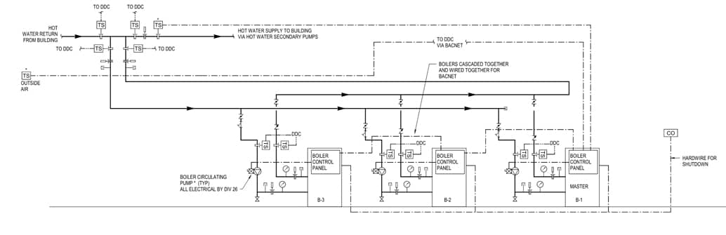
Figure 1 – System Diagram
Initial Investigation
Upon initial investigation, it was discovered that the service bypass valve for the PRV was open, allowing 50 PSI of makeup water to be introduced to the top of the system. The bypass valve was then closed, and the PRV was found to be set at 40 PSI. The PRV was then adjusted to a more appropriate 10 PSI, given its location at the top of the system. Excess pressure was bled off, and the system returned to normal operation. However, the system began to experience rapid pressure spikes again after just 10 minutes of normal operation.
Root Cause Analysis
Further investigation revealed that the building automation system (BAS) communication was intermittently lost, causing the system temperature setpoint to default from the BAS-supplied 140°F to an internal communication fault setpoint of 180°F. In addition, the expansion tank for the system had been temporarily disconnected to repair a small leak, which left no room for the system to accommodate thermal expansion.
With these new findings, it was concluded that the pressure spikes were caused by thermal expansion due to the setpoint drastically increasing when communication was lost without room in the system for the volume of the water to expand.
Resolution
The communication issue was resolved by changing some communication settings through the BAS. The internal communication fault setpoint was changed to a lower setpoint of 160℉. The expansion tank was reconnected to the system, and normal operation resumed, with the system functioning as designed.
Importance of Proper Makeup Water PRV Settings
This case study highlights the importance of setting the makeup water PRV to the appropriate pressure based on where the water is introduced in the system. For systems fed from the bottom, the PRV is usually set at a higher pressure to accommodate the increased head pressure caused by the vertical distance the water must travel. In contrast, systems fed from the top require a lower PRV setting, as the water is introduced directly to the highest point in the system, eliminating the need to overcome significant head pressure.
Understanding Thermal Expansion and Its Impact
The case study also emphasizes the importance of understanding thermal expansion in a hydronic heating system. When the system’s temperature setpoint increased, and the expansion tank was disconnected, there was no room for the system to accommodate thermal expansion. This led to rapid pressure spikes and could have resulted in damage to the system components or even a catastrophic failure.
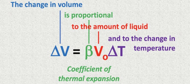
Figure 2 – Thermal Expansion Equation
Expansion Tank Bladder
Properly setting the bladder air pressure of a thermal expansion tank is also crucial for maintaining system performance and preventing pressure issues. Typically, the air pressure in the bladder should be set equal to the static pressure of the system at the tank’s location before it is connected. In the case of the system described in the case study, the expansion tank was located at the top of the system, where the factory setting was adequate due to the lower static pressure at the highest point in the system. However, if the expansion tank were located at the bottom of the system, proper adjustment of the bladder air pressure would be much more critical. In a bottom-located scenario, the static pressure would be significantly higher due to the increased head pressure from the vertical distance the water must travel. In such cases, the bladder air pressure must be set according to the specific system requirements and height of the building to prevent pressure imbalances and ensure the expansion tank functions effectively in managing pressure fluctuations caused by thermal expansion.
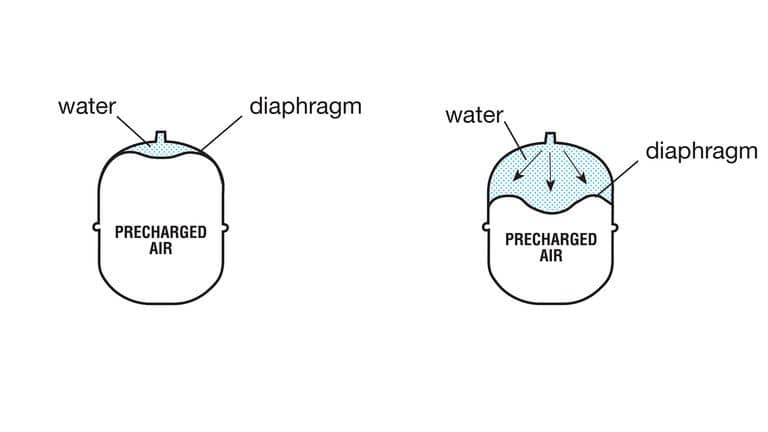
Figure 3 – Expansion Tank Diagram
Conclusion
This case study underscores the importance of proper makeup water PRV settings and understanding thermal expansion in maintaining a well-functioning hydronic heating system. By adjusting the PRV settings based on the system’s location and ensuring that the system can accommodate thermal expansion, operators can prevent pressure spikes, potential system damage, and ensure efficient and effective building temperature control.
Written by Chris Monday, CxA.