A long-term client built a new Welcome Center on their campus. As you can imagine, a Welcome Center is place where all students are to feel comfortable and it should provide an inviting atmosphere. During construction we were asked to place a priority on the chilled water system. The Second Floor air handling unit could not achieve the supply air setpoint and the general contractor continually informed us he had over a million dollars in woodwork finish-out in a space that could not control temperature.
Chilled Water System Balancing
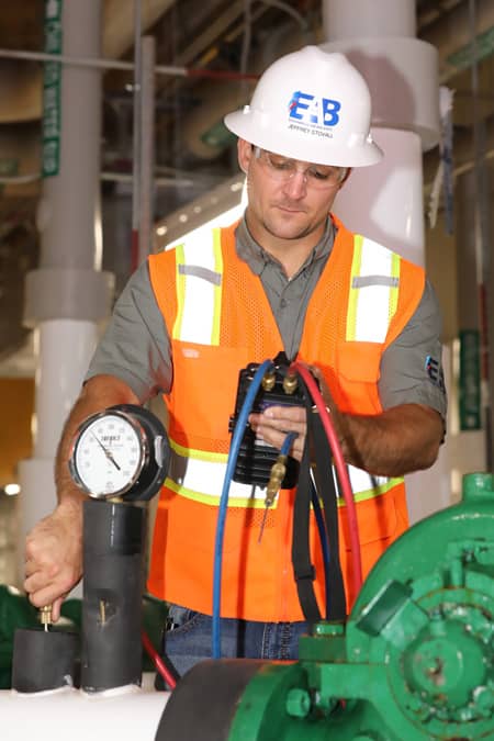
As we began our chilled water balance, we started by measuring shut-off head for the pump. The pressure ports made available to us were in the standard location on the pump flange. The data indicated we would be using the same curve the manufacturer suggested on the pump curve, meaning the impeller checked out to be the same size. Our next step in the process was to check the capacity of the pump with the valve 100% open and confirm it was a non-overloading pump. As we measured the pressures of the pump operating under this condition, we read the discharge pressure as lower than the suction pressure.
Wait, let’s read those pump pressures again…yep, discharge pressure was less than the suction pressure. As my partner and I stared at each other in disbelief wondering how it was even possible, we then went into full investigation mode. Taking pressures here, taking pressure there. What were the pressures at the pumps in the campus central plant? What was the pressure of the make-up water systems? Were the pumps at the main central plant super-charging the pump in this building? Was the make-up water set too high and causing problems? What were the chilled water temperatures at the AHU on the Second Floor? The chilled water supply temperature was measured to be 58°F. I told my partner, “No, I need the supply temperature.” He says to me, “That is the chilled water supply temperature!” Hmm…let’s drop downstairs and measure at on the First Floor. The chilled water supply temperature was 46°F. Okay, so why was it not getting to the Second Floor? Upon further investigation, the piping was air-locked. Once we bled the air, the chilled water supply at the unit on the Second Floor dropped to 46°F and the unit could finally provide cool air to the floor; however, this was short lived.
Pump Inspection Discovery
We recommended the pump be turned off each evening so the air could rise to the highest point in the system and each morning, bleed the air in the piping and start the pump again. Unfortunately, the Second Floor began to warm up again. The air had been removed but the supply water temperature now remained in the 50s. Back to the pump we go…
We took pressures again, just to confirm. Yep, suction pressure was still higher than the discharge pressure. The air handling unit located in the same mechanical room as the pump had an automatic flow control device installed in the chilled water return piping. We verified it was in control with a minimum of a 2 PSI differential across the device. As we read the device, we measured 1.5 PSI. Hmm…the unit that was literally in the same room was low on waterflow. We then verified the actual water flow of the pump with an ultrasonic flow meter. The ultrasonic flow meter was installed in an ideal location with an estimated 15 feet of straight pipe on the discharge side of the pump, located between the pump and the air handling unit in the same room. The ultrasonic indicated 25 GPM was being provided to the system from a pump submitted for 150 GPM. Hmm…NONE of this data makes sense.
Let’s think about this, what do we know? 25 GPM measured from a pump selected for 150 GPM, the autoflow device on the unit in the same room was not in control, and the unit on the Second Floor was not receiving 46°F. It had to be something with the pump.
With a little more co-worker conversation about what the data was indicating and what we felt the problem was, the decision was made to ask the contractor to disconnect the suction side of the pump and investigate for a possible restriction. The thought process was that the suction side being restricted was not allowing the pump to move the water through the piping. Somewhat makes sense. We guessed that was why the suction pressure was higher than the discharge pressure. The restriction on the suction side could be causing a higher pressure. When the pump was taken apart, we found the cleanest, shiniest, most pristine pump impeller I had ever seen.


Hmm…we weren’t expecting that! The contactor had disconnected the discharge side of the pump as well so the pump could be rotated, and we had a better view of the inlet of the pump (and took these amazing photos showing how WRONG we actually were).
We stared at the inlet of the pump, asking the rhetorical question of “What in the world could it be now?” My partner said “Hey, take a look at this on the discharge side of the pump…” and the conversation continued. “Looks like some type of debris.” “What do you think, from the flushing of the system?” “Maybe we break it apart and clean it out…”


As we inspected the discharge of the pump closer, we discovered an obstruction that was hard and made of metal. The best we could tell, it was part of the casting of the volute when the mold of the pump was made.
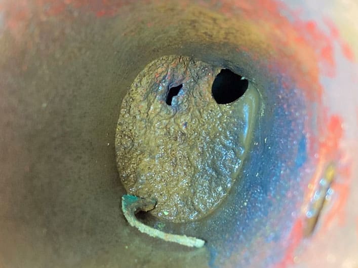
The two small openings were allowing the 25 GPM to pass through and distribute to the system. The part that was so confusing for us was when we verified shut-off head of the pump, it plotted exactly as the manufacturer suggested on the submittal data. It was discovered that the pressure port being used to measure the discharge pump pressure was after this obstruction. So, when the discharge valve was closed, the pump forced water through these two small openings and the pressure equalized between the obstruction and the closed discharge valve. Ta-daa! Shut-off head checks out. When the discharge valve was opened, the obstruction (located between the pump impeller and the pressure port we were using), showed a lower discharge pressure than the suction pressure.
The temporary fix for the contractor was to swap the pump with one of the heating water pumps to provide cooling to the building until the manufacturer representative could schedule time to inspect the pump. We were not present the day the representative arrived, but we were told the pump was taken to their shop where the metal piece was honed out to the full size opening of the discharge of the pump. Our testing data today shows all is well.
Written by Brian Moss.