

Data center commissioning verifies that a facility’s power, cooling, and control systems meet the owner’s project requirements, from design review and factory testing through functional and integrated systems testing. In an N+1 duty/standby arrangement, that verification should cover the standby unit’s behavior while it is off, not only its response when a failover is triggered.
A test script can prove the running unit works and the transfer to the spare happens, and still miss what the standby unit does while it is commanded off. Faults that develop over hours in an idle unit are the ones a short test window misses.
Below: where that gap sits in the commissioning levels, how a standby unit fails while off, what correct standby looks like by equipment type, and how to write the observation into the FPT script.
What Data Center Commissioning Verifies, and Where the Gap Sits
ASHRAE Guideline 0-2019 states that its purpose is to describe a commissioning process “capable of verifying that the facility and its systems meet the Owner’s Project Requirements (OPR).” That process runs from predesign through design, construction, and occupancy and operations. ASHRAE Guideline 1.1-2025, “Application of the Commissioning Process to New HVAC&R Systems,” augments Guideline 0 and Standard 202 with HVAC&R-specific technical detail.
How the Data Center Commissioning Levels Break Down
Most data center projects organize testing and commissioning into levels, although firms number them differently (Level 1 to 5, Level 0 to 6, Level 0 to 7). The numbering is an industry convention, not a single published standard, and some frameworks add design or closeout stages. A commonly used five-level framework runs:
- Level 1: Factory witness testing
- Level 2: Delivery and installation checks, usually tracked on system verification checklists
- Level 3: Startup
- Level 4: Functional performance testing
- Level 5: Integrated systems testing
The Gap Level 4 and Level 5 Can Leave Open
In Engineered Air Balance’s view, the gap in commissioning data centers sits in what the last two steps leave out. Level 4 functional tests verify the running equipment against its sequence of operations, and Level 5 integrated tests verify how systems behave together, including through transitions. Unless the script defines a standby observation window, neither observes the idle unit across the hours it spends in standby.
In an N+1 or 2N design, the owner is paying for redundant capacity that is ready. Guideline 0 frames commissioning as verification against the OPR. When the OPR includes ready redundant capacity, verifying standby is part of that job.
How N+1 and 2N Redundancy Change What You Have to Test

N is the capacity a system needs to meet its design load. N+1 adds one component beyond that, so the system still meets the load with any one unit out; depending on the design, the units share the load or run as duty and standby. 2N duplicates the infrastructure with independent distribution, each side able to carry the full load. This article is about the units a sequence commands off or stages out, and what they do while they wait.
Uptime Institute’s Tier Classification System describes capacity, maintainability, and fault tolerance in its own terms, without N+1 or 2N labels:
- Tier II adds “redundant capacity components” for power and cooling. Uptime lists engine generators, energy storage, chillers, cooling units, UPS modules, pumps, heat rejection equipment, fuel tanks, and fuel cells.
- Tier III is “concurrently maintainable,” with no shutdowns required when equipment needs maintenance or replacement.
- Tier IV is fault tolerant, so that when equipment fails, “IT operations will not be affected.”
As Uptime Institute’s explanation of the Tier system puts it, the Tier Standard “states the desired results, not how to achieve them.” That is the opening for commissioning: the standard defines the outcome, and the test script proves it.
Failover Is an Event. Standby Is a State.
A failover lasts seconds or minutes. Standby lasts until the next rotation or failure. A script that tests only the event leaves the state unobserved, even though N+1 redundancy in a data center depends on it.
A Standby Unit Can Fail While It Is Off
The failure category is a component doing something other than what it was commanded to do. The LEED v4 enhanced commissioning credit, in its monitoring-based commissioning path, lists “out-of-sequence operation of systems components” among the elements used to evaluate performance. LEED’s monitoring-based path is optional; its plan covers energy- and water-consuming systems and runs into the first year of occupancy, and USGBC’s guidance advises running that monitoring concurrently with functional performance testing whenever possible. The failure mode is the same.
EAB saw this on a Houston hospital’s domestic hot water system, where the steam control valve on the heat exchanger commanded off in an N+1 pair (DWH-1) was letting steam through intermittently while commanded closed. It was a fault that only showed up in multi-hour BAS trend data, and the full story is in EAB’s article on trending during functional performance testing.
Data center equipment has its own versions of this problem.
Fan Arrays: Backdraft Dampers That Don’t Seal
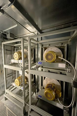
EAB’s Durwood Lassiter, III, writing on testing fan arrays in fan failure mode, states that in an N+1 or greater array “a system test in fan failure mode is necessary.” In his test scenarios, every fan runs in normal operation, and the fan failure test takes one out of service to confirm the others can cover it. Each inlet backdraft damper “must be able to close when a fan is not in operation” to prevent recirculation inside the unit. A stopped fan with a leaking damper still reads “off” on a status screen.
Parallel Pumps: Check Valves That Don’t Hold
Writing in POWER about power plant circulating water systems, mechanical engineer Michael F. Czyszczewski notes that “check valves do not provide positive shutoff” and that “reverse flow will make an unpowered centrifugal pump spin backwards.” The risk is high vibration and damaging loads on the motor and bearings. The standby pump in an N+1 set is in a similar position: unpowered, piped in parallel with running pumps, and relying on its check valve to prevent reverse flow through an idle pump.
Chillers: Isolation Valves That Don’t Close
Gil Avery’s guide to converting chiller plants to all-variable flow, published in HPAC Engineering, calls for chiller branch isolation valves: “Install a two-position chilled-water isolation valve in the branch to each chiller.” Where the sequence isolates an idle chiller, its valve command and position feedback both belong in the test. Position feedback shows the valve moved, not that it shuts tight; Avery allows metal-seated butterfly valves where isolation is their only job.
What “Off” Actually Tells You
EAB’s trend plans put command and feedback side by side for this reason: a status point that says “off” shows the unit is not running. It does not show that the valve closed, the damper sealed, or the check valve is holding. Proving standby takes:
- The command sent to the unit
- The feedback confirming the unit responded
- The variable a fault would disturb
What Correct Standby Looks Like, Equipment by Equipment
For each piece of redundant equipment, define correct standby before testing, then trend the points that would show a departure from it.
The point list follows the general pattern in EAB’s trending guidance (controlled variable, setpoint, command, feedback, equipment status, and the source of any expected disturbance), applied here to the unit that is off.
- Generators: Heating engine coolant during standby is general practice for keeping a generator ready to start.
- Fan arrays: Lassiter notes that “the fan failure mode will show an increased fan RPM” on the remaining fans. That is what the fan-failure test checks.
- UPS modules: Keep the standby observation to status and event points. UPS functional and failover testing have their own FPT and integrated systems testing procedures.
Writing the Standby Observation Into the FPT Script
EAB’s trending article covers how to build a trend plan: point selection, logging interval, duration, and acceptance criteria. Here is what changes when the unit under test is the idle one.
Rotate Deliberately
Where the design rotates lead/lag or duty/standby equipment, schedule the rotation so each redundant unit spends a documented window as the idle unit during acceptance. EAB’s guidance for staged equipment is to trend at least one complete lead/lag rotation.
Set Standby Acceptance Criteria Before the Window Opens
Write these down first:
- The idle unit stays in its commanded state
- Command and feedback agree within an acceptable margin
- There are no state changes the approved sequence does not call for
Where a manufacturer control tolerance exists, it is the starting point.
Match the Logging Interval to the Symptom
Choose the logging interval against the symptom you expect to see, not the fault’s own frequency. Where the system supports it, use change-of-value logging for binary points such as equipment status and damper open/closed, and confirm it is configured to record the transitions you need to see. For another example of BAS trend data put to work during commissioning, see EAB’s article on tuning a cooling tower PID loop during commissioning.
Plan for Missing Points
Where the BAS or EPMS lacks the points, history retention, or reliable timestamps, specify temporary data logging or added instrumentation in the commissioning plan before FPT begins. Before reading any trend, confirm the point mapping, timestamps, record completeness and source-sensor accuracy, and check that each feedback point reports the equipment rather than echoing its command.
Treat a Failed Standby Result Like Any Other Deficiency
It follows the same closeout:
- Log it in the issue log
- Identify the root cause
- Document the correction
- Re-trend the unit
- Get sign-off from the engineer of record, or the party the commissioning plan names, before closing
Cost and Schedule
Where usable BAS or EPMS records are available remotely, trend review may not need an extra site visit. The main cost drivers are analysis time and window length, plus any added instrumentation, investigation, and retesting. Running the window parallel to other commissioning work helps keep the schedule impact small. Post-handover trend review is scoped separately.
How Standby Testing Fits With Failover and Integrated Systems Testing
The standby observation complements integrated systems testing rather than replacing it. IST evaluates how the systems perform together under defined scenarios, and standby observation adds a check on how the system behaves over the window before the next transition.
Uptime Institute’s Tier Certification of Constructed Facility involves a site visit by Uptime consultants and ends with a complete “pull the plug” test. Even that is a moment in time.
Redundancy also creates unplanned interactions. In an EAB article on redundancy that failed during integrated systems testing, Jeremy White, P.E., describes two AHUs at a vivarium facility split across A and B power feeds for redundancy. When a life safety ATS momentarily lost power, fire/smoke dampers began closing, static pressure rose in the common supply duct, and high-static safeties shut down both units.
Where the commissioning plan allows, run the standby window before IST, so a unit that isn’t truly ready is found before the integrated test relies on it.
EAB’s Hyperscale Data Center Experience
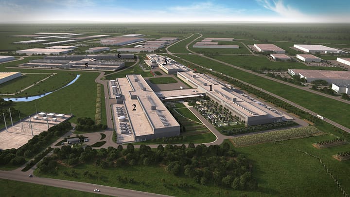
EAB’s Fort Worth data center project covered a 2.5 million sq ft campus in Fort Worth, Texas, with:
- Six buildings and 22 data halls
- A cold-storage facility and three administration areas
- Two central plants and ten industrial water plants
Each data hall used 12 fan arrays with 15 fans each (180 fans), delivering approximately 1,270,000 cfm. EAB describes it as one of the largest fan array air delivery systems it has tested.
EAB’s scope covered testing and balancing of the HVAC systems, sensor calibration verification, and control sequence verification. The team developed custom test procedures for supply and return airflow and for piping failure testing, plus a field-testing apparatus that fits over individual fans. As then project supervisor Paul Lewis put it, “what would have normally taken 31 days to complete, took our team only seven days to complete.”
Lewis, EIT at the time, presented at CxEnergy 2023 on TAB’s role at hyperscale data centers, a fan array airflow verification procedure that “improved testing time from weeks to days,” hydronic equipment and systems testing, and TAB and commissioning collaboration during L3 and L4 commissioning. Paul Lewis is now a Project Manager at EAB, holds P.E. and TBE credentials, and manages Meta data center projects in Temple, Texas, and Jeffersonville, Indiana.
Lassiter’s guidance is that “every fan needs to be checked for proper rotation, amperage, and RPM.” In a data hall with 180 fans, that standard calls for all three checks on each of the 180.
Frequently Asked Questions
What are the levels of data center commissioning?
Levels run from factory testing through installation checks, startup, functional performance testing, and integrated systems testing. They are an industry convention, not a single published standard, so frameworks number them differently (Level 1 to 5, 0 to 6, or 0 to 7).
What does N+1 mean in a data center?
N is the capacity a system needs to meet its design load. An N+1 data center adds one component beyond that, so it still meets the load with any one unit out; the units may share the load or run as duty and standby. 2N duplicates the infrastructure with independent distribution.
Is failover testing enough to verify an N+1 system?
No. Failover testing verifies performance through a defined failure scenario. It doesn’t show whether the idle unit behaved correctly while commanded off, which is where leaking dampers, passing valves, and check valve problems show up.
How long should a standby unit be observed during commissioning?
Base it on equipment behavior, not a fixed number of days. EAB’s guidance for staged equipment is to trend at least one complete lead/lag rotation.
Does trend review add site visits or cost?
Not necessarily. Where usable BAS or EPMS records are available remotely, trend review may not need an extra site visit, and the main cost drivers are analysis time and window length.
Prove the Spare Before Handover

The spare you paid for is only redundancy if it is ready, and the commissioning script is where that gets proven.
If you are planning mission-critical commissioning for a data center or another critical facility, talk with our team about building standby-state checks into your functional performance test scripts. EAB’s building commissioning services include project-specific functional performance tests written to the control sequences of the equipment installed. For the data center work behind this article, including the Fort Worth hyperscale campus, see EAB’s mission-critical facilities projects.